- 您现在的位置:买卖IC网 > Sheet目录1221 > IRPLLNR2U (International Rectifier)BALLAST 32W/T8 120V AC IR21571
�� �
�
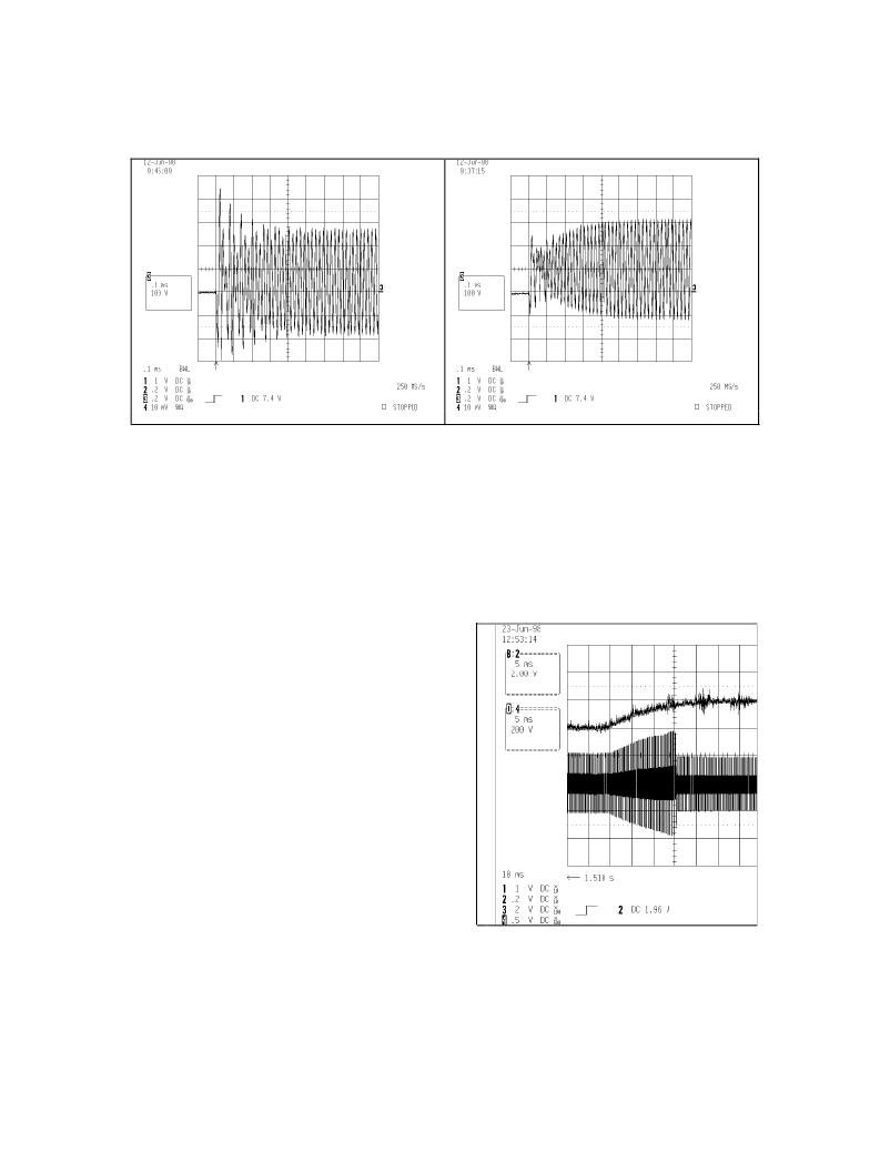
�Figure� 7:� Typical� lamp� voltage� at� startup;�
�f� Startup� =� f� P� reheat�
�Figure� 8:� Improved� lamp� voltage� at� startup;�
�f� Startup� >� f� P� reheat�
�The� duration� of� the� Preheat� mode� as� well� as� which� mode� of� operation� the� ballast� is� operating� in� is�
�determined� by� the� voltage� on� the� CPH� pin� of� IC2.� At� the� completion� of� the� UVLO� mode,� Preheat�
�mode� is� entered� and� an� internal� current� source� is� activated� at� the� CPH� pin� of� IC2� which� begins� to�
�charge� up� capacitor� CPH.� The� ballast� remains� in� the� Preheat� mode� until� the� voltage� on� the� CPH�
�pin� of� IC2� exceeds� the� Ignition� Ramp� mode� threshold� (4V).�
�Ignition� Ramp� Mode�
�At� the� completion� of� the� Preheat� mode� (4V� <� CPH�
�pin� <� 5.1V)� the� ballast� switches� to� the� Ignition� Ramp�
�mode� and� the� frequency� ramps� down� to� the� ignition�
�frequency.� The� frequency� ramping� is� accomplished�
�by� turning� off� the� internal� open� drain� MOSFET� on�
�the� RPH� pin� of� IC2� (see� Figure� 1,� IR21571� block�
�diagram).� Resistor� RPH� is� no� longer� connected� di-�
�rectly� in� parallel� with� resistor� RT.� The� shift� in� frequency�
�does� not� occur� in� a� step� function� but� rather� with� an�
�exponential� decay� because� of� capacitor� CRAMP� in�
�series� with� resistor� RPH� to� ground.� The� duration� of�
�this� frequency� ramp� is� determined� by� the� time� con-�
�stant� of� the� RC� combination� of� capacitor� CRAMP�
�and� resistor� RPH.� The� minimum� frequency� of� oscil-�
�lation� occurs� at� the� end� of� this� ramp� and� is� deter-�
�mined� by� resistor� RT� and� capacitor� CT.� During� this�
�ramping� downward� of� the� frequency,� the� voltage�
�across� the� lamp� increases� in� magnitude� as� the�
�frequency� approaches� the� resonant� frequency� of�
�the� LC� load� circuit� until� the� lamp� ignition� voltage�
�10�
�Figure� 9:� Upper� trace:� voltage� on� capacitor�
�CRAMP� during� Ignition� Ramp� mode�
�Lower� trace:� Lamp� voltage� during� Ignition�
�Ramp� mode.�
�www.irf.com�
�发布紧急采购,3分钟左右您将得到回复。
相关PDF资料
IRPLLNR4
BALLAST UNIV INP FLUOR IR2166
IRPLLNR5
KIT BALLAST UNIV FLUOR 54W TL5
IRPLLNR7
KIT UNIV ELEC BALLAST FLUOR LAMP
IRPLMB1E
KIT DESIGN BALLAST 220VAC
IS-418-TR1509-12
POWER SUPPLY 240VAC FOR DEV KIT
IS-DEM KIT-2
SMARTDISPLAY DEMONSTRATION KIT 2
IS-DEV KIT-1
SMARTSWITCH DEVELOPMENT KIT 1
IS-DEV KIT-2
SMARTSWITCH DEVELOPMENT KIT 2
相关代理商/技术参数
IRPLLNR3
制造商:IRF 制造商全称:International Rectifier 功能描述:Universal Input Linear Fluorescent Ballast using the IR2167
IRPLLNR4
功能描述:BALLAST UNIV INP FLUOR IR2166 RoHS:否 类别:编程器,开发系统 >> 过时/停产零件编号 系列:- 标准包装:1 系列:- 类型:MCU 适用于相关产品:Freescale MC68HC908LJ/LK(80-QFP ZIF 插口) 所含物品:面板、缆线、软件、数据表和用户手册 其它名称:520-1035
IRPLLNR5
功能描述:电源管理IC开发工具 Uni Inpt Lin Fluor Ballast 54W TL5 Lamp RoHS:否 制造商:Maxim Integrated 产品:Evaluation Kits 类型:Battery Management 工具用于评估:MAX17710GB 输入电压: 输出电压:1.8 V
IRPLLNR7
功能描述:电源管理IC开发工具 Flourescent Ballast Using IRS2166DPBF RoHS:否 制造商:Maxim Integrated 产品:Evaluation Kits 类型:Battery Management 工具用于评估:MAX17710GB 输入电压: 输出电压:1.8 V
IRPLMB1E
功能描述:KIT DESIGN BALLAST 220VAC RoHS:否 类别:编程器,开发系统 >> 过时/停产零件编号 系列:- 标准包装:1 系列:- 类型:MCU 适用于相关产品:Freescale MC68HC908LJ/LK(80-QFP ZIF 插口) 所含物品:面板、缆线、软件、数据表和用户手册 其它名称:520-1035
IR-POST-B
制造商:Knoll Systems 功能描述:Single Target IR Repeater Kit with Black Postage Stamp Receiver 制造商:KNOLL SYSTEMS 功能描述:IR REPEATER COMPLETE KIT BLACK POSTAGE STAMP RECEIVER
IRPP3624-05A
制造商:International Rectifier 功能描述:5 AMP SINGLE PHASE SYNCHRONOUS BUCK POWER+ CHIPSET REFERENCE - Bulk 制造商:International Rectifier 功能描述:DEMO BOARD KIT FOR 3624SPBF 5A 制造商:IR 功能描述:Single Phase 5 A Synchronous Buck Reference Design
IRPP3624-12A
功能描述:电源管理IC开发工具 12 AMP 1 PHASE SYNC BUCK PWR+ RoHS:否 制造商:Maxim Integrated 产品:Evaluation Kits 类型:Battery Management 工具用于评估:MAX17710GB 输入电压: 输出电压:1.8 V